

Current Sense Resistor Original Manufacturer: Precision and Reliability for Your Circuit Designs
2026-10-13
When every millivolt counts, settling for off-the-shelf current sense resistors isn't an option. That's where an original manufacturer steps in—Milliohm delivers the tight tolerances and long-term stability your circuit designs demand.
Why Your Current Sense Resistor Choice Matters More Than You Think
Most designers treat the current sense resistor as a minor supporting component, something you pick from a table and move on. But that tiny part sits directly in the measurement path, and every micro-ohm of variation, every degree of temperature drift, and every parasitic inductance in its leads shows up as error in your control loop. A resistor that looks fine on paper can quietly degrade accuracy in overcurrent protection, battery fuel gauging, or motor torque control, especially at low sense voltages where a few millivolts of offset swamp the signal.
The physical construction matters just as much as the marked resistance. Thick-film parts are cheap but drift with temperature and load cycling, while bulk metal or foil resistors offer far better stability when the current changes rapidly. Kelvin sensing terminals aren't just a nice-to-have; without them, the solder joint resistance and copper trace drops get folded into your measurement. And in switching regulators, the parasitic inductance of a long, narrow resistor package can create voltage spikes that confuse fast comparators, leading to nuisance trips or missed faults.
Then there's the thermal side. A sense resistor's temperature coefficient and power rating interact in ways a simple Ohm's law calculation won't reveal. Run it too hot, and the resistance shifts, which changes the current reading, which changes the heat dissipation, and you end up with a nonlinearity that's hard to debug. Choosing a resistor with margin in both wattage and temperature stability is often cheaper in the long run than chasing false overcurrent events or recalibrating a product after field failures.
Precision Isn’t Just a Spec: How Resistor Construction Affects Accuracy
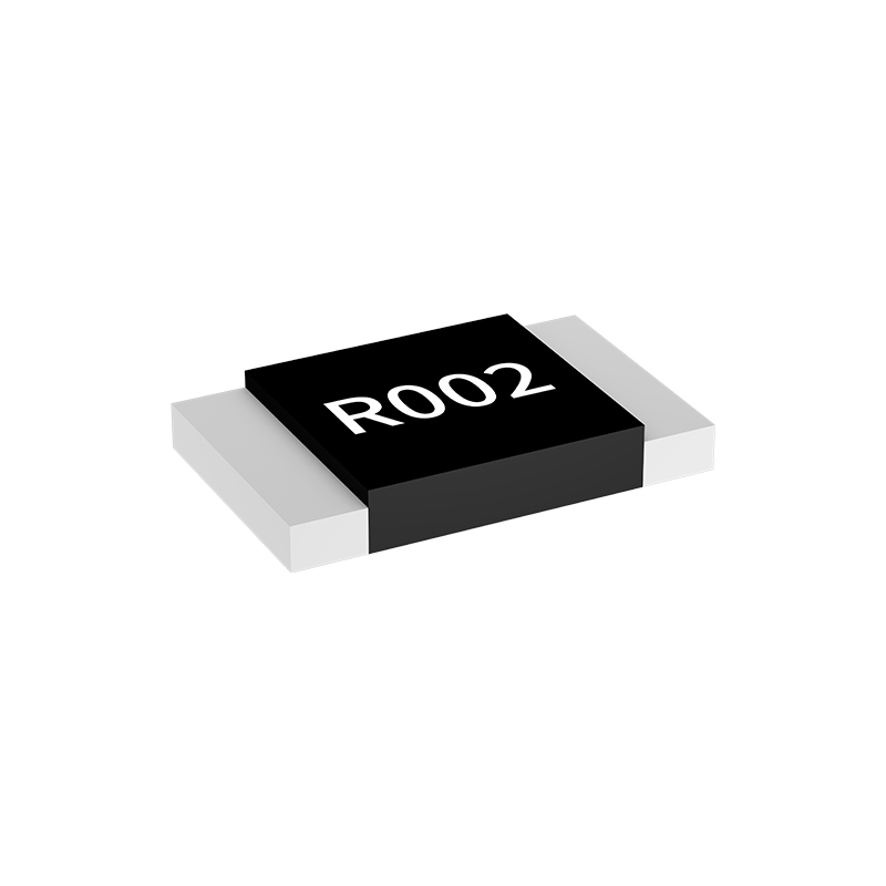
Datasheets often open with tolerance and temperature coefficient, but those two specs rarely tell you how a resistor will perform when it is actually mounted, powered, and exposed to real thermal gradients. Construction plays a larger role than many designers expect. Thick film, thin film, foil, and wirewound elements each carry their own noise signature, parasitic behavior, and drift mechanism. A thick film part marked 0.1% may look precise on paper, yet in a high-gain stage its excess noise and voltage coefficient can erode effective resolution long before temperature drift becomes a concern.
The trimming method is equally telling. Laser spiral cuts used on thick film resistors create localized current crowding and microfractures that introduce excess noise and long-term instability. Foil and some thin film designs rely on bulk etching or pattern adjustment instead, avoiding those stress points. Termination style adds another layer of error. Dissimilar materials at the lead-to-element junction form thermocouples; if one end of the resistor sits slightly hotter than the other, a small DC offset appears that no tolerance specification will capture.
Geometry and substrate finish the picture. A long serpentine pattern on a ceramic body may look compact, but it increases parasitic capacitance and inductance, pulling accuracy down in fast or high-frequency circuits. Short, low-profile foil elements with planar terminations improve thermal uniformity and minimize stray reactance. Understanding these construction details gives you a far better predictor of in-circuit accuracy than a single printed tolerance number ever will.
Reliability Under Stress: Thermal Cycling, Surge, and Long-Term Drift
Most field failures don't happen at nominal conditions—they emerge when a part is pushed through rapid temperature swings, hit with unexpected voltage spikes, or left running for thousands of hours at the edge of its spec. Thermal cycling, for instance, works like a slow-motion fatigue test: solder joints expand and contract at different rates than the board beneath them, eventually cracking in ways that a single thermal shock would never reveal. Similarly, surge events—whether from inductive switching, lightning, or hot-plug transients—test not just the clamping diodes but the entire input protection network's ability to absorb energy without latching up. Then there's long-term drift, the quiet killer: a precision reference that shifts a few millivolts over a year, or a capacitor whose ESR creeps upward until a power rail starts ringing. Real reliability isn't about surviving one stressor; it's about how these mechanisms compound.
Designers often fool themselves by testing each stress in isolation. A converter that handles 1000 thermal cycles and a separate 2 kV surge may still fail after 200 cycles plus a modest surge, because micro-cracks from thermal stress lower the dielectric's surge withstand. Long-term drift adds another layer: parameters like leakage current and threshold voltage move slowly, so a circuit that works after 1000 hours might oscillate or brown out at 5000 hours once marginal components cross their tipping points. The only honest way to assess reliability is to combine stressors in realistic sequences—thermal cycling followed by surge, then accelerated aging with periodic parametric sweeps. That's where the hidden interactions show up.
Field data from industrial and automotive applications consistently shows that the majority of unexplained failures trace back to one of these three mechanisms interacting with another. A solder joint weakened by thermal cycling becomes a high-resistance path that surges find easier to arc across. An aged electrolytic capacitor with elevated ESR lets a transient ring longer, stressing semiconductors downstream. Fixing this requires moving beyond datasheet limits: derating alone won't save you if the failure mode is synergistic. Instead, you need accelerated life testing that mimics the actual stress profile—not just the maximum ratings—and you need to monitor drift continuously, not just at the end of the test. Components that look healthy at t=0 can be quietly degrading in ways that only reveal themselves under the right combination of thermal, electrical, and temporal stress.
Matching Resistor Performance to Your Circuit’s Real Current Path
Resistor datasheets give you a neat, single number for resistance, but that value assumes a uniform current distribution across the entire resistive element. In a real circuit, the current rarely flows that way. It might crowd into one corner of a thick-film chip because of via placement, or snake along a serpentine trace where the outer edges carry more current than the inner bends. When the actual current path deviates from the ideal, the resistor’s effective value shifts, and you start seeing localized hot spots that can degrade long-term stability or even cause premature failure.
Think about a current-sense resistor in a switching supply. You pick a 10 mΩ part for its low loss, but the PCB traces feeding it are just as wide as the resistor’s terminations, so the current enters from one side and exits the other in a fairly straight line. That’s fine. Now take the same resistor and rotate it 90 degrees on a tight layout, forcing the current to make a sharp turn right at the termination. The current bunches up near the inner corner, the effective resistance goes up by several percent, and that corner gets noticeably hotter than the rest of the package. Your measurement accuracy suffers, and the temperature coefficient of resistance starts working against you.
To keep resistor performance aligned with the actual current path, look beyond the schematic symbol. Check where the current enters and exits, and give it a low-impedance route that spreads the flow across the full width of the termination. For high-frequency or fast-switching circuits, also account for the return path and any parasitic inductance from vias or long pads. Small layout changes—widening a trace, adding a copper pour on the backside, or shifting the resistor a few millimeters—can bring the real-world performance much closer to the datasheet spec without changing a single component value.
When Off-the-Shelf Isn’t Enough: Custom Current Sense Solutions
Standard current sense amplifiers work well until you hit a combination of requirements that no single datasheet covers. Maybe the common-mode voltage swings beyond 80V, or the shunt value needs to be so small that offset drift becomes the dominant error. In battery-powered designs, the quiescent current of an integrated solution can exceed the entire sleep budget. These mismatches push engineers away from off-the-shelf parts toward a tailored signal chain.
A custom approach often starts with a precision op amp and a discrete resistor network, but the real work lies in managing layout parasitics, thermal gradients, and gain error over temperature. You might add a guarded Kelvin connection, select a low-inductance shunt, or use a floating supply to handle high-side sensing at several hundred volts. Digital calibration can remove systematic offset and nonlinearity, turning a mediocre analog front end into a repeatable measurement system.
The payoff shows up in places like fuel gauges that need microamp resolution next to 50A pulses, or motor drives where phase current must be reconstructed from a single shunt without blanking time errors. Off-the-shelf parts force you to accept trade-offs; a custom current sense path lets you trade design time for exactly the bandwidth, accuracy, and power draw your product demands. That trade is not always cheap, but for many high-performance designs it is the only path that actually closes the spec sheet.
Avoiding the Hidden Costs of Low-Quality Current Sense Resistors
A current sense resistor that drifts a few milliohms under load rarely draws attention on the bill of materials, but it quietly forces compromises elsewhere. Design teams compensate by derating power stages, adding calibration routines, or oversizing heat sinks—none of which show up as a line item tied to the resistor itself.
The real expense surfaces later, when inconsistent temperature coefficients cause measurement error that mimics load changes. Field returns, unexplained efficiency drops, and intermittent overcurrent faults often trace back to a part that looked identical on the datasheet but behaved differently at 85°C or after thermal cycling. Re-qualifying a substitute mid-production costs far more than the savings from a cheaper resistor.
Worse, parasitic inductance in poorly trimmed resistive elements can distort fast current waveforms, leading to false trip events and controller instability. Choosing a resistor with tight TCR, low thermal EMF, and stable element construction removes those hidden variables—so the current loop stays predictable across the full operating range without silent margin erosion.
FAQ
An original manufacturer controls the resistive alloy formulation, trimming process, and terminal welding in-house. That matters because small changes in current density or weld resistance can shift the effective resistance value. Distributors may carry parts from mixed production batches, but they cannot adjust or guarantee those process details. With the original source you get lot-level traceability and direct access to application engineers who know exactly how the part behaves under pulse loading.
Ask for the manufacturer's lot traceability report and check the date code against their internal production records. Genuine original parts usually carry a manufacturer-specific marking format and packaging label that includes the factory location. If the supplier cannot provide a certificate of conformance with the original company's letterhead, treat it as a grey-market part. Also compare the measured temperature coefficient and short-time overload performance against the official datasheet limits.
For low-ohm shunts, focus on resistance tolerance, temperature coefficient of resistance, thermal EMF, and the four-terminal Kelvin connection structure. Tolerance gets you the initial accuracy, but TCR determines how much that accuracy drifts with board temperature. Thermal EMF becomes noticeable in high-current layouts where heat flows across the resistive element. A four-terminal design separates the current path from the sense path, so PCB trace resistance does not corrupt the measurement.
Yes, most original manufacturers offer custom alloy thickness, trimming targets, and terminal shaping. For example, if your layout only has space for a 2512 package but you need a 0.3 milliohm value with a tight TCR, they can adjust the alloy cross-section and laser trim pattern. The lead time is longer than off-the-shelf parts, but you avoid stacking multiple resistors or compromising accuracy. Provide your steady-state current, pulse profile, and ambient temperature range up front so the factory can estimate the hot-spot temperature before committing to a design.
For harsh environments, check that the part has passed AEC-Q200 stress tests: high-temperature exposure, temperature cycling, moisture resistance, and short-time overload. Pay special attention to load life stability under full rated power at maximum operating temperature. A resistor that shifts more than one percent after 1,000 hours at rated power is going to cause calibration drift in the field. Also request the sulfurization test if the board may be exposed to oil or rubber components, because silver-based terminations can corrode and open.
Thermal EMF comes from the junction between the resistive alloy and the terminal material. When a temperature gradient appears across the resistor, that junction generates a small DC voltage which the sense amplifier cannot distinguish from the current signal. In a 1 milliohm shunt carrying ten amps, the measurement signal is only ten millivolts, so even a few microvolts of thermal EMF create a meaningful error. Original manufacturers reduce it by selecting matched alloy pairs and by using symmetrical terminal construction so the thermal gradients cancel.
Metal alloy shunts are usually the better choice for battery monitoring because they offer lower resistance values with excellent long-term stability and lower TCR. Metal film parts are fine for higher resistance ranges, but below a few milliohms they become difficult to manufacture with tight tolerance. Alloy resistors also handle pulse currents better without drifting. The trade-off is that alloy parts can be slightly more expensive and physically larger, but for coulomb counting and state-of-charge estimation the measurement stability is worth it.
Use a true four-terminal Kelvin connection and route the sense traces as a differential pair away from high-current paths. Place the sense resistor close to the measurement IC to reduce loop area, and keep the high-current traces wide and short. Avoid putting vias in the current path near the resistor pads, because via resistance adds to the measured drop. If you are using a two-terminal resistor in a high-current design, make sure the sense lines tap directly at the pad edges rather than further down the trace.
Conclusion
Choosing a current sense resistor often gets treated as an afterthought, but the part you pick quietly shapes measurement accuracy and circuit stability. Precision goes far beyond a datasheet number—construction details like element material, termination style, and trimming method alter how the resistor behaves under real loads. Thermal cycling, surge events, and long-term drift can expose weaknesses that a simple tolerance figure never reveals. A resistor that looks fine on paper may shift enough over temperature or time to corrupt feedback loops, battery monitoring, or motor control. Even small changes in resistance value can translate into meaningful error when currents are high or when the sense voltage is low, so the manufacturing process behind the component becomes a critical part of your signal chain.
The actual current path in your layout matters just as much as the component itself, so a design that works well with one resistor may fail with another unless you account for parasitic inductance and heat spreading. When standard parts fall short, working directly with an original manufacturer opens the door to custom geometries, alloys, or mounting options that fit the circuit instead of forcing the circuit to fit the part. Low-cost alternatives often hide expenses in field returns, recalibration, or overdesign, while a properly matched current sense resistor keeps your design predictable from prototype to production. That kind of reliability is not something you can add later—it has to be built into the part from the start, which is why the original manufacturer’s control over materials and process matters for any serious circuit design.
Contact Us
Contact Person: Yuying Gao
Email: [email protected]
Tel/WhatsApp: +86 18926013721
Website: https://en.milliohm.net/