

Custom Ultrasonic Bubble Sensors: Precision Air Bubble Detection for Critical Fluid Lines
2026-09-19
In critical fluid lines—whether in bioprocessing, semiconductor fabrication, or medical device manufacturing—even a microscopic air bubble can compromise product integrity, disrupt precise dosing, or damage sensitive equipment. Traditional bubble detectors often struggle with varying tube materials, low flow rates, or non-invasive installation constraints. That’s where Siansonic steps in with custom ultrasonic bubble sensors engineered for real-world complexity. Unlike off-the-shelf alternatives, these sensors are tailored to your exact tubing dimensions, fluid acoustics, and detection thresholds, ensuring reliable, repeatable air bubble detection without false alarms. In this post, we’ll explore how Siansonic’s precision ultrasonic technology works, why customization matters for critical applications, and what sets their approach apart from conventional solutions. If you’ve ever lost sleep over microbubbles slipping past your quality checks, read on.
Your Process Can't Afford a Stray Bubble
In precision fluid paths, a single unexpected air bubble acts like a tiny wrecking ball. It compresses under pressure, then releases energy at the worst possible moment, creating voids, uneven coatings, or cavitation damage that only shows up after the batch ships.
The real cost isn't just scrap parts. It's the troubleshooting time spent chasing intermittent failures that don't reproduce on the bench. A stray bubble can hide in a dead leg or low point, then break loose when line speed changes or temperature shifts, ruining a run that was otherwise dialed in.
Prevention means looking beyond the obvious vent valves. It requires mapping every high point, checking fitting orientations, and questioning whether your degassing step actually removes dissolved gas or just gives it a place to collect. Until you treat bubbles as a process variable rather than an annoyance, they will keep finding ways to interrupt production.
How Ultrasonic Waves Catch What Optical Sensors Miss
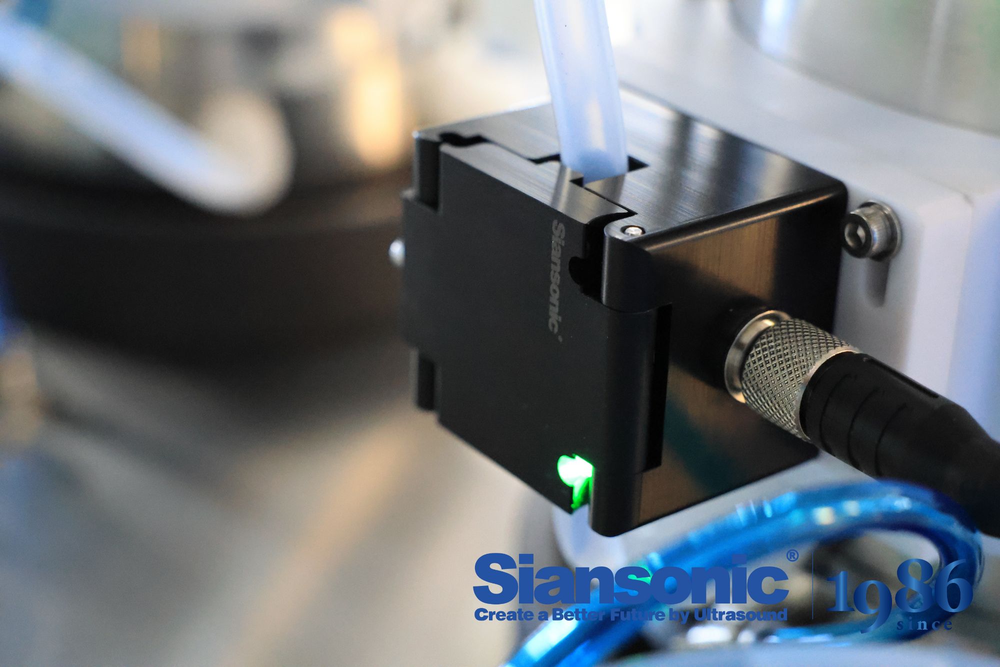
Optical sensors rely on light, so anything that blocks or bends light creates blind spots. Dust, smoke, steam, or even a glassy surface at the wrong angle can render them useless. Ultrasonic waves, by contrast, travel as pressure ripples through air. They bounce off physical boundaries regardless of color, transparency, or ambient lighting, making them far less picky about what they see.
In practice this matters a lot on a foggy loading dock where a camera would only catch a gray blur. An ultrasonic sensor still picks up the solid edge of a pallet or a person stepping into its range. Because the echo travels at a known speed, the time-of-flight calculation remains stable even when the target has no visual contrast at all. That reliability is why industrial tanks and robotics teams often pair optical systems with ultrasonic ones, each covering the other's weak spots.
There is a second advantage that is easy to overlook. Optical sensors must be kept clean and angled precisely, while ultrasonic transducers can function behind a protective mesh or in messy conditions. The sound wave does not care if the surface is matte, glossy, or transparent. It only cares that there is a change in acoustic impedance, which almost any solid object provides.
Tailored Frequency Tuning for Specific Fluids and Tubing
Matching ultrasonic output to the exact fluid in the line isn't a one-size-fits-all job. Low-viscosity solvents respond well to higher frequencies that produce finer cavitation bubbles, while thicker oils often need lower frequencies to generate enough mechanical force for thorough cleaning or processing. Ignoring this mismatch leads to weak results or, worse, damage to sensitive tubing walls.
The tubing itself imposes another layer of constraints. Rigid stainless steel can handle aggressive frequency sweeps, but softer polymers and thin-walled glass require careful damping to avoid resonance fractures. By tuning the drive signal to the tubing's natural harmonic range, the system delivers energy where it's needed without rattling fittings loose or creating dead zones at bends.
Operators who take the time to profile each fluid-and-tubing pair typically see sharper process consistency and longer equipment life. A quick impedance check during setup reveals whether the transducer is fighting the load or coupling cleanly, and small adjustments from there often cut cycle times by a noticeable margin.
Non-Invasive by Design to Protect Sterility
The core idea behind non-invasive sterility protection is to keep every fluid path sealed until the moment of connection. Instead of relying on needles or open ports, the system uses pre-sterilized disposable sets with membrane-sealed couplings. When two sides meet, the membranes peel back or push together without exposing the inner channel to room air, so the product never touches a non-sterile surface.
This approach shifts the burden from operator technique to physical design. Aseptic transfers happen through closed mechanical valves or sterile connectors that require no flaming, wiping, or manual alignment under a hood. Because there is no puncture step, there is no coring debris or accidental sharps contact. The sterile barrier remains intact even if the user hesitates or adjusts grip mid-connection.
The result is a process that behaves the same way in a busy cleanroom as it does during a field validation run. By removing the invasive action, the design eliminates the most common route for microbial ingress while leaving fewer variables for training and environmental control to manage.
Real-World Roles in Dialysis, Bioreactors, and More
Membranes are not just lab curiosities. In dialysis, they act as selective barriers that let waste products like urea and excess salts pass out of the blood while keeping larger proteins and blood cells where they belong. The pore size, surface charge, and material chemistry all get tuned to match the specific toxins a patient's kidneys can no longer remove, and the flow rates on either side of the membrane are carefully balanced to avoid stressing the blood.
Bioreactors lean on membranes for a different reason: keeping cells alive and productive while controlling what enters and exits the culture. A hollow-fiber setup can deliver oxygen and nutrients from one side while pulling metabolic byproducts away from the other, mimicking the capillary networks that tissues rely on in the body. The same principle shows up in industrial enzyme production, wastewater treatment, and even in the clarification step for fruit juices, where membranes replace older filtration methods to keep flavor compounds intact.
Outside these examples, membrane-based systems quietly manage gas separation in power plants, desalination in coastal cities, and controlled release in some drug delivery patches. The common thread is selective transport—letting some molecules cross while blocking or slowing others—which makes membranes a practical tool whenever a process needs a physical boundary that also does chemical work.
Balancing Sensitivity and Stability Under Dynamic Flow
Flow conditions rarely hold still. A system tuned too tightly to one snapshot of demand will overshoot when traffic patterns shift an hour later. The practical answer is not a fixed coefficient or a single damping factor, but a layered response that treats fast-moving noise differently from slower structural change. Short-term jitter gets filtered through a fast loop that reacts without committing hard resources; longer drifts are absorbed by a slower loop that adjusts baselines only after repeated confirmation. This split keeps the system responsive to real spikes without making it brittle to transient bursts.
The harder part is deciding what counts as signal in a stream that keeps changing its own statistics. A queue depth that looks alarming at 2 a.m. may be meaningless at noon. Rather than rely on absolute thresholds, the control layer should track relative deviation: how far the current state sits from its own recent envelope, and whether that gap is widening or closing. When the gap widens quickly, sensitivity can rise for a short window; when it narrows, stability takes back the reins. This gives an adaptive middle ground where the same logic works during lulls and overloads without needing a mode switch.
In practice, the most robust designs make sensitivity itself a first-class variable rather than a preset. Each adjustment carries a small confidence score derived from how consistent the recent past has been. If the past hour is erratic, the system leans toward stability and ignores minor excursions; if the past hour is smooth, it can afford a sharper reaction to sudden change. That way the trade-off is never resolved once and for all—it is renegotiated continuously, which is exactly what a moving, unpredictable flow demands.
FAQ
The sensor sends high-frequency sound waves across the tubing. Liquid transmits the signal efficiently, but when even a tiny air bubble passes between the transducer and receiver, the acoustic impedance changes dramatically, causing a sharp drop in received signal strength. That drop is interpreted as a bubble event.
Yes, the electronics can be calibrated for specific wall thickness, tubing hardness, and fluid type. For example, softer silicone tubing and rigid PFA require different gain settings, and the firmware can store multiple profiles for quick changeover between product lines.
Custom designs let you match the transducer frequency, housing geometry, and output signal to your exact flow path and bubble size threshold. Instead of designing your equipment around a generic sensor, the sensor is built around your critical dimensions and failure criteria.
Applications where a single air embolism or dry pump event can ruin a batch or damage equipment—think hemodialysis, bioreactor perfusion, inkjet printing, semiconductor chemical delivery, and pharmaceutical filling lines. These systems often need sub-microliter bubble sensitivity.
Advanced models use differential signal processing and periodic auto-zeroing to distinguish between slow fouling and fast bubble transients. Some versions also include a reference channel that compensates for gradual acoustic or optical drift.
No, most custom ultrasonic bubble sensors are clamp-on or snap-on. They use dry coupling or a thin acoustic gel pad, so the fluid path remains sealed and sterile. For high-pressure lines, the housing can be integrated into a manifold without direct fluid contact.
Typical options include open-collector alarm output, 4–20 mA analog signal proportional to bubble size, RS-485 with Modbus, and a configurable digital pulse for each detected bubble. Custom logic can also latch an alarm until manually reset.
Depending on tubing diameter and flow rate, a well-tuned system can detect bubbles as small as 0.5 microliters in a 3 mm ID tube. In larger lines, the threshold scales roughly with cross-sectional area, but the goal is always to flag bubbles before they reach a critical downstream component.
Conclusion
A stray air bubble in a dialysis circuit or bioreactor feed line is more than an inconvenience—it can compromise patient safety or ruin a batch. Custom ultrasonic bubble sensors are built around that reality. Instead of relying on optical clarity, they read acoustic impedance shifts as bubbles pass between transducers, which means opaque tubing, stained fluids, and high-viscosity media don't blind them. The real advantage comes from tailoring the ultrasonic frequency to the exact fluid and tubing pair; a one-size-fits-all sensor often drifts into false alarms or misses micro-bubbles entirely. Because the transducers clamp onto the outside of the line, sterility stays intact—nothing touches the fluid path.
In practice, these sensors earn their place in hemodialysis, single-use bioreactors, and transfusion systems, where dynamic flow makes detection harder. Rather than chasing a fixed threshold, custom units tune both sensitivity and damping so they track bubbles reliably across pulsatile or varying flow rates without crying wolf. The result is not just a detector but a fitted instrument—matched to the line's material, wall thickness, and the acoustic quirks of the liquid itself. That kind of precision keeps small bubbles from becoming large problems.
Contact Us
Contact Person: Ivy Zhang
Email: [email protected]
Tel/WhatsApp: +86 1081502288
Website: https://www.siansonic.com/