

OEM Residual Current Transformer: Key Factors for Reliable Selection and Integration
2026-08-17
When OEMs choose a residual current transformer, the wrong decision rarely shows up on day one—it surfaces later as nuisance tripping, failed compliance tests, or compromised safety. Achieving reliable selection and integration demands attention to factors that datasheets often gloss over. In this article, we’ll examine those critical points, from core materials to mechanical fit, and share practical insights from Xiasen’s work with industrial and energy customers.
Why standard core materials stumble in pulsating DC-link residual currents
Standard magnetic cores are often specified for clean sinusoidal or pure DC conditions, yet pulsating DC-link residual currents create a lopsided excitation that few datasheets anticipate. The current carries a meaningful DC offset with superimposed ripple, which pushes the operating point along the B-H loop into a biased region. Without a true negative half-cycle to reset the flux, the core gradually accumulates remanence. This makes the effective permeability collapse well before the rated current is reached, so the inductance value becomes unstable and varies with load, temperature, and ripple amplitude.
There is a less obvious penalty: the ripple and transient spikes within the pulsating current force the magnetic domains through minor hysteresis loops at elevated flux density. Core losses rise sharply, and the DC bias brings the material closer to its saturation knee. Once the core begins to brush against saturation during each switching cycle, the choke or filter no longer presents a predictable high impedance. Ferrites offer low high-frequency loss but suffer from poor DC bias tolerance; silicon steel saturates later but generates excessive eddy-current heating under fast edges. This mismatch explains why off-the-shelf cores often run hot, whine audibly, or let common-mode noise leak through in pulsating DC-link applications.
Even when the average residual current looks modest, the peak of the ripple can repeatedly nudge the core into local saturation. Adding an air gap helps avoid deep saturation, but it also lowers the effective permeability and forces a larger core volume to achieve the same inductance. Simply oversizing the core cannot fully solve the problem because the root cause is the material’s inability to handle a DC-biased, ripple-heavy flux swing without drifting into nonlinear territory. Recognizing this limitation is the first step toward selecting purpose-built powder cores, gapped ferrites, or composite designs that tolerate pulsating residual currents.
From milliamps to motor inrush: sizing for the full current spectrum
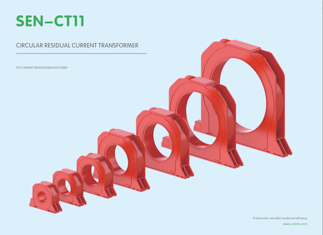
Focusing only on steady-state current is a common trap. A loop that draws a few milliamps at idle can spike to 90 A the moment a motor contactor closes. If your sensor or protection device is sized for the running load alone, that inrush will either clip the measurement or trip the breaker before the machine ever reaches full speed.
The low end matters just as much. You need enough resolution to see a 3 mA leakage or a 10 mA control signal without it being buried in noise. That calls for a device with a wide dynamic range, not just a high maximum rating. Look at both the smallest current you must detect and the largest transient you must survive, then check the full-scale accuracy, overload rating, and response time against that entire span.
A practical setup often combines two approaches: a sensitive shunt or Hall-based sensor for the milliamp range, paired with a clamp or current transformer that handles high inrush. If you prefer a single instrument, choose one with true auto-ranging and a high crest factor, so it can track the quiet periods and still capture the starting surge without saturating.
Twisted leads and tight corners: precision in physical integration
Twisting a lead into a tight corner isn't just about making it fit—it's about knowing exactly how much bend the conductor can take before performance degrades. In precision assemblies, the distance between the stripped end and the first point of flex matters just as much as the radius itself. A fraction of a millimeter too sharp, and you've introduced a stress riser that will quietly fatigue under vibration or thermal cycling. The trick is to route the lead so that natural curvature does the work, letting the wire's own stiffness set the path instead of forcing it with pliers or a fingernail.
When you're working with tight corners, the insulation is often the first casualty. It kinks, whitens, or splits at the outer edge of the bend, exposing the conductor to shorts or corrosion. A good practice is to make the bend in one smooth, continuous motion—no micro-adjustments—and to keep the lead slightly longer than the drawing suggests, because a lazy curve beats a hard right angle every time. If the layout forces a sharp turn, consider forming a small loop or an S-curve instead, which distributes the stress over a longer section and gives you a little compliance for assembly tolerances.
Physical integration is where electrical design meets mechanical reality. A board that works on the bench can fail in the enclosure because a wire was forced against a standoff or pinched under a lid. The best assemblers develop a feel for when a lead has been pushed past its elastic limit—it goes soft, the copper work-hardens, and the whole joint becomes a liability. Precision here means leaving just enough slack for service loops but not so much that leads tangle or rub. Every twist and turn should look intentional, as if the wire grew that way, not as if it was wrestled into submission.
EMC reality check: shielding tactics that survive the inverter's noise
Ground your expectations in the field: most shielding failures trace back to overlooked return paths, not the shield material itself. A braided copper sleeve looks robust on the bench, but if it's bonded at only one end, it becomes a radiating antenna for the inverter's switching harmonics. The trick is to treat the shield as a current-carrying conductor, not a passive wrapper. Run a low-inductance bonding strap at both ends, keeping the path back to the drive's chassis as short as a hand's width. That alone often kills the worst common-mode spikes before they reach the analog sensors.
Cable selection matters more than thickness. Foil-and-braid combinations handle high-frequency noise better than heavy braid alone, because the foil provides full coverage against electric-field coupling while the braid carries the low-frequency fault currents. But don't ignore installation geometry—ties and routing can undo a perfect shield in minutes. Keep signal cables away from motor leads, cross them at right angles when inevitable, and never coil excess shield drain wire into a loop. A loop acts like a secondary winding, picking up the inverter's PWM edge and injecting it straight into your feedback loop.
Finally, accept that some noise leaks through even the best shielding. Add a common-mode choke at the drive output or a ferrite clamp on the encoder cable to suppress what the shield can't stop. Tune these elements together—shield first, then filter the residue. Measure the result with a high-bandwidth scope probe across a low-value resistor in the ground path, not just by eye. The inverter's noise is fast, repetitive, and sneaky; your shielding tactics need to be equally stubborn.
Getting the burden right: how the relay's input impedance changes everything
Most people treat a relay's input as a simple on/off threshold, but the truth is its impedance quietly dictates how the entire sensing circuit behaves. A low-impedance input can load down a current transformer enough to skew the secondary waveform long before the trip point is reached. The result isn't just a small error—it's a systematic distortion that shifts the effective pickup and can fool even experienced technicians into blaming the wrong component.
On the other hand, an overly high input impedance might look harmless on a spec sheet, yet it invites noise coupling and slow settling that wreak havoc in fast protection schemes. The burden resistor value, whether internal or external, has to work with the CT's magnetizing curve and the relay's own front-end capacitance. Getting this balance wrong means the relay's advertised accuracy class becomes meaningless, and the actual operating point drifts with temperature, wiring length, and even the phase angle of the fault current.
Once you grasp that the relay input is a parallel load across the CT secondary, the design decisions become clear: choose a burden that keeps the CT in its linear region, account for the relay's input capacitance at the highest harmonic you care about, and verify the impedance with a real signal, not a DC meter. A small change in that input impedance—say, from 0.1 Ω to 0.5 Ω—can shift a sensitive earth-fault relay's pickup by several percent, enough to turn a nuisance trip into a missed protection event.
Beyond the datasheet: what accelerated life testing reveals about long-term drift
Datasheets provide a snapshot of component performance under nominal conditions, but they rarely capture how parameters shift over thousands of hours in the field. Accelerated life testing (ALT) pushes devices beyond rated stress levels to expose latent degradation mechanisms, revealing long-term drift in offset voltage, bias current, or reference accuracy that static specifications simply cannot convey.
One of the most striking findings from ALT is that drift is rarely linear. Early life often shows a rapid settling phase as package stresses and surface charges stabilize, followed by a slower, asymptotic drift that can persist for years. This means a part that meets its initial accuracy spec may still cross a system-level threshold well before the expected end of life, especially in precision analog or sensor front-ends.
By combining multiple stress factors—temperature, humidity, voltage, and thermal cycling—test engineers can build drift models that extrapolate to real-world mission profiles. These models help designers select components not just by datasheet limits, but by predicted drift margin over the full service life, ultimately reducing field failures and calibration intervals.
FAQ
Focus on the residual operating current range, burden compatibility with the connected relay, accuracy class under non-sinusoidal conditions, rated frequency span, and thermal drift. Many datasheets look good at 50 Hz sine waves but fail when leakage contains rectifier harmonics. Ask for the error curve across the intended temperature window and at low excitation levels. A high-permeability core with a tight tolerance on secondary turns usually gives the best repeatability.
Look beyond initial accuracy. The core material should have low aging drift and minimal remanence. Encapsulation quality matters: voids or poorly bonded epoxy allow moisture ingress that changes insulation resistance and shunt capacitance. Request accelerated life test data, especially thermal cycling from cold start to full load. If the supplier cannot show drift over 1,000 cycles, treat long-term stability as unproven rather than assumed.
Power electronic loads produce DC leakage components and high-frequency common-mode currents. A conventional FeSi or ferrite core can be driven into saturation by even small DC offsets, causing the transformer to lose sensitivity exactly when a genuine insulation fault appears. Design around it by selecting a nanocrystalline core with high DC tolerance, or by adding a small air gap if the burden allows, and verify the response with a composite DC-plus-AC test waveform.
Shield grounding at both ends creates ground loops that inject noise into the secondary. Running the secondary leads parallel to power cables couples common-mode transients. Placing the burden resistor far from the relay input adds inductance. Route twisted-pair leads directly to the relay, ground the shield only at the measurement end, and keep the burden resistor as close as practical to the transformer terminals.
When the busbar aperture is non-standard, the residual current range is unusually low, or the mounting must survive high vibration and washdown. Customization also pays off if you need an integrated burden, a specific phase angle for compatibility with an existing relay, or a sealed housing that survives outdoor humidity. If you are only adjusting sensitivity, a standard part with an external burden is usually enough.
Request evaluation samples and test them with waveforms that match your real application, not just a clean sine wave. Apply short-duration residual pulses, harmonics, and temperature steps. Measure the secondary output into the actual relay input impedance. Compare several samples for consistency. If the vendor only provides a certificate from a 50 Hz sine test, it tells you very little about field behavior.
High-permeability materials like permalloy or nanocrystalline give strong output at small residual currents but can be more prone to remanence after a large fault. Ferrite is cheap and stable but less sensitive. Nanocrystalline often provides the best compromise because it combines high permeability with low coercivity and good temperature stability. The wrong core choice can create a transformer that is either deaf to small faults or trips on harmless transients.
Yes. The primary conductor should pass through the aperture centered and perpendicular to the core plane. Off-center conductors distort the magnetic field and reduce repeatability. Keep adjacent phase conductors at least one aperture diameter away to avoid cross-coupling. If multiple turns are used for low-current measurement, wind them symmetrically. Any air gap around the bushing should be filled to prevent vibration-induced movement.
Conclusion
Selecting an OEM residual current transformer that survives real-world inverter duty starts with acknowledging why conventional core materials fall short when faced with pulsating DC-link residual currents. Standard silicon steel or simple ferrite designs saturate quickly under the asymmetric flux swings common in variable-speed drives, leading to false trips or, worse, blind spots in protection. The transformer must be sized not just for the milliampere leakage thresholds required by safety standards but also for the full current spectrum from steady-state leakage to motor inrush transients. This means choosing a core geometry and material with enough headroom to avoid saturation during high-frequency common-mode bursts while still resolving low-level residual currents with acceptable linearity. A robust selection approach treats the current transformer as a dynamic element, not a fixed-ratio device, and derates the core cross-section based on worst-case DC bias and temperature rise rather than relying on nominal 50/60 Hz ratings.
Physical integration adds another layer of risk that datasheets rarely capture. Twisted secondary leads and tight corner routing introduce stray capacitance and inductive coupling that can distort the residual current waveform before it reaches the relay. Practical mounting demands careful attention to conductor spacing, shield termination, and avoidance of ground loops—especially when the transformer sits inches away from a switching inverter. EMC shielding must be designed to survive the inverter's broadband noise spectrum, not just pass a bench test, and the burden presented by the relay's input impedance changes everything: a few ohms of extra resistance can shift the phase response enough to degrade trip accuracy. Beyond those immediate concerns, accelerated life testing on properly loaded transformers reveals long-term drift in core permeability and insulation resistance, which often goes unnoticed in short-term qualification. Successful integration therefore hinges on treating the residual current transformer, its wiring, and the relay input as one tightly coupled system, with margins validated under thermal cycling, vibration, and continuous common-mode stress rather than ideal laboratory conditions.
Contact Us
Contact Person: Liu Mengyang
Email: [email protected]
Tel/WhatsApp: 8618727589233
Website: https://www.cnlrm.com/en/